Roy Williams
Jochem Hauser and Ralf Winkelmann
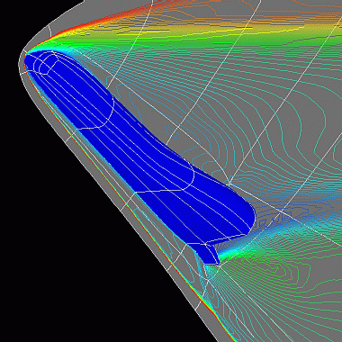
Figure 1 depicts a Mach 9.8 Navier-Stokes flow, where the freestream pressure (65 Pa) corresponds to reentry in the outer atmosphere. Half of the Halis is shown in blue, with the Mach contours shown on the symmetry plane. Note that the bow shock is well resolved, even when it is very close at the nose, and the shock-shock interaction behind the body flap is also well represented.

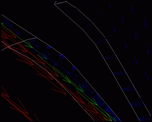
This flow is difficult computationally, not only because of the thin viscous boundary layer, but also because there is a "temperature boundary layer"; the skin of the craft is assumed to be held at a constant temperature (300 degrees K). Therefore, the boundary layer has not only large momentum flux within it, but also large heat flux. The most complex part of the flow is at the rear of the craft, where the body flap projects downward. This body flap is exposed to extreme stress, both mechanical and thermal; thus, it is essential to model this region well. Experiments indicate a small recirculation zone at the hinge between the fuselage and the body flap, and discerning this was one of the objectives of the work described herein.
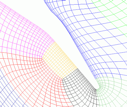
The ParNSS (Parallel Navier-Stokes Solver) code was used to compute this flow. ParNSS uses a multiblock grid with second-order, GMRES-implicit steps, and van Leer's flux splitting scheme in a MUSCL formulation. The grid, which has 980,000 points with 32 points to resolve the boundary layer, was made with GridPro software. Figure 2 illustrates part of the surface grid near the body flap, showing a modified topology to enhance the local resolution. This topological flexibility allows a substantial increase in local resolution without over-refining the far field.

Numerous runs were performed on the Intel Paragon at Caltech to discover an optimum convergence to steady state. We investigated sequencing of explicit and block-implicit steps, choice of preconditioners, and how to choose the (spatially non-uniform) time steps. Communication inefficiency was no problem because, by using block-implicit step, each processor solves a set of large, sparse linear systems for each time step, with a communication only after each of these large tasks. Up to 135 processors were used for the 192-block grid, but the varying block-size provides an upper limit on efficiency: the smallest block has 462 points and the largest has 2,560 points, so it becomes difficult to distribute the blocks evenly for larger numbers of processors.

Figure 3. Recirculation zone at the body-flap hinge. The red and green arrows show the fast, supersonic flow that has passed through the bow-shock. The adjacent small, blue arrows point in the opposite direction, showing recirculation.
References